
Article Written by:
Stephen L. Quarles, Ph.D.,
IBHS Senior Scientist and South Carolina Wind and Hail Underwriting Association Chair
Home and Building Exposure to Wildfires
Building ignitions during wildfires occur when a component or components of a home or building are exposed to one or more of the three basic wildfire exposures. These exposures include 1) burning embers (also called firebrands), 2) direct flame contact, and 3) radiant heat. Burning embers are the most important cause of home ignitions. When they land near or on a building they can ignite near-by vegetation or accumulated debris on the roof or in the gutter, or enter the building through openings (an open window or vent for example) and ignite furnishings in the building or debris in the attic. Near-building ignitions will subject some portion of the building to either a direct flame contact exposure, where the flames actually touch the building, or a radiant heat exposure, the heat you feel when standing near a campfire or fireplace. The vulnerability of a building to radiant heat depends on the intensity and duration of the exposure. The extent of damage will also depend on the construction material.
As part of its research effort to study and understand the vulnerabilities of buildings subjected to wildfire exposures the Insurance Institute for Business & Home Safety (IBHS) has developed the capability of simulating ember and radiant heat exposures on building components and assemblies at their Research Center in Richburg, South Carolina. The primary objective of this research is to reduce the likelihood of wildfire-caused building ignitions in communities located in wildfire-prone areas. The goal of this article is to provide a summary of the findings from recent testing at the Research Center.
Exposure to Embers (Firebrands)
Developing Ember Generation Capabilities
In collaboration the USDA Forest Service and the Savannah River National Laboratory, IBHS developed the capability of injecting burning embers into the wind stream in the large testing chamber, effectively reproducing ember storms typically observed during wildfires. The design of the ember generator was based on a similar devise developed at the National Institute of Standards and Technology (Manzello 2008). This article provides a summary of, and some of the lessons learned or confirmed from this recent ember exposure study. The ember generating equipment, discharging embers, is shown in Figure 1. The building that was designed and built for the ember exposure studies is shown in Figures 2 and 3.

| Figure 1. The IBHS ember generating equipment consists of five metal chambers, uniformly spaced across the test chamber, and located below grade in a five-foot wide pit. Each chamber was loaded with approximately 40 pounds of combustible bark mulch and wood dowels. A propane gas burner was located at the bottom of each chamber to ignite the bark mulch and wood dowel mixture and a fan pushed the burning embers up through the vertical ducts and into the wind stream of the wind tunnel. |
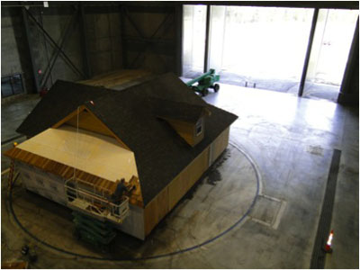
| Figure 2. An overview photograph of the test building. The test building was placed on a turn table in the large test chamber. Use of a Dutch-hip design allowed for the installation of three different roof coverings. Asphalt fiberglass composition shingles and untreated wood shakes (being installed) are shown here. A clay barrel tile roof covering was installed at the opposite end of the building from the wood shake covering roof section. |

| Figure 3. View of the test building showing near-building combustible mulch and vegetation, the pine needle accumulation in the valley of the asphalt composition roof shingles and pine needle accumulation in the gutters. The gable end vent is also circled. |
Building Components (Ember Exposure)
During a series of tests, different components on the building were investigated to evaluate their potential vulnerability to embers. The components included the different roof coverings, a roof dormer and roof valley, gable end and eave vents, gutters, windows and window screening and siding. The impact of combustible mulch located next to the exterior wall was also evaluated, both in terms of ease of ignition by embers and damage to the exterior siding from the resulting flame contact exposure. The building was rotated on a turntable to enable expose of different roof coverings, roof designs and other building component to wind-blown embers. During the series of tests reported here, wind speeds were limited to 10 to 15 miles per hour.
The Roof
Figures 4 and 5 show the results of ember-started fires in the field of the roof (i.e., away from the roof edge or roof to wall intersection). The untreated wood shakes ignited as a result of the ember exposure. These ignitions were localized and the fires, as seen here, were initially small. As seen in Figure 4, flaming combustion occurred in some locations whereas smoldering (glowing) combustion occurred in other locations. The fire at the circled location (Figure 4) burned through the wood shakes and the underlying roof sheathing. The roof fires were extinguished early, but a post-fire investigation indicated that the fire at this location almost burned into the attic. If left unchecked, the fire would have burned into the attic and spread over the roof surface.
As seen in Figure 5, the embers ignited the pine needle debris in the valley of the Class A fire rated asphalt fiberglass composition shingle roof covering. The shingles in this valley were installed using a woven installation technique (i.e., the valley construction consisted only of the roof covering material and did not use metal flashing). As seen in this photograph, the combustible “asphalt” component of the roof covering was damaged by the burning pine needles. However, as a result of the protection offered by the fiberglass component and the granular covering, the Class A roof covering was not threatened in terms of the fire penetrating into the attic.

| Figure 4. Ember ignitions on the untreated wood shake roof. At one location (circled), the fire burned through the wood shakes and most of the roof sheathing before the fires on the roof were extinguished. |

| Figure 5. Post-test photograph of the Class A fire rated asphalt composition (fiberglass) roof covering, after the pine needles were ignited by embers and burned. |
Roof-to-Siding Intersections
Pine needles and other combustible debris can accumulate at roof-to-siding intersections, such as can occur at a dormer or the roof of a split level house. When ignited by embers, the resulting fire will impinge on the siding (Figure 6). As observed in Figure 5, a Class A fire resistant roof covering can withstand a flame contact exposure from ignited debris that has accumulated on an asphalt composition shingle roof. The adjacent siding and sheathing in the dormer construction must provide similar protection, or it will become the vulnerable component on the roof. It is important to keep accumulated debris to a minimum, but if present and ignited by embers, the vulnerability to the roof won’t be the Class A roof covering, but rather the components used to construct the dormer. In this example, a noncombustible fiber cement siding was used as the siding material, but in this case, the combustible under-eave soffit material would also be vulnerable, particularly toward the back end of the dormer where the roof-to-soffit distance is shorter (circled, Figure 6).

| Figure 6. This dormer is representative of a vulnerability to embers that occurs on a “complex” roof, specifically at roof-to-siding intersections. |
Vents
Based on the studies to date, vents whose face was perpendicular to the wind flow carrying the embers were more vulnerable to the entry of embers. Examples of these vents were gable end (Figure 7) and the under eave vents in open-eave construction. Vents in open-eave construction are located in the blocking members (i.e., 2 x 4 lumber fastened between the roof rafters or trusses at the top of the exterior wall and immediately below the roof sheathing) and are sometimes called frieze block vents. Ember entry into the attic through vents in soffited (boxed-in) eaves was minimal. Most of the ember entry observed in soffited-eave construction resulted from embers entering through the gap between the fascia and roof sheathing (circled, Figure 8). These embers could have been generated by the ember generators and/or the burning pine needle debris in the metal gutter that was attached to the fascia. Ember accumulation in this area was minimal when a metal drip edge was installed at the roof edge to cover this gap.
All of the vents evaluated in this study incorporated either 1/8- or ¼-inch mesh metal screening. Screening did not eliminate the entry of embers but did reduce the number and size of embers entering the attic. These results are in agreement with those presented by Manzello, et al. (2011).

| Figure 7. A view from inside the attic showing the accumulated embers (no longer burning), lodged in the screen of the gable end vent. |

| Figure 8. The burned out embers shown on the surface of the soffit material entered through the gap between the top the fascia and edge of the roof sheathing (circled). The drip edge would be placed on the outside edge of this joint. |
Gutters
Embers easily ignited both the pine needle debris that was placed in the gutters and the pine needle and bark mulch placed at the base of the exterior wall. Both vinyl and metal gutters were used in these tests. In Figure 9, the gutter on the left was vinyl and that on the right was metal. Once debris in the vinyl gutter ignited, it detached from the fascia and fell to the ground. The burning debris contributed to the burning mulch at the base of the wall that was also ignited by embers. The metal gutter stayed in place, and the burning debris provided a flame contact exposure to the fascia and sheathing at the edge of untreated wood shake roof. The burning debris in the vinyl and metal gutters ignited the wood shake roof near the edge of the roof.
| Figure 9. Wind-blown embers ignited debris in the metal (right) and vinyl (left) gutters and mulch at the base of the wall. In this photograph, the vinyl gutter (left) has partially detached from the fascia and is falling to the ground. Note also embers on the window screen. As long as the screen was intact, larger embers were prevented from entering into the interior of the building. |
Combustible Siding
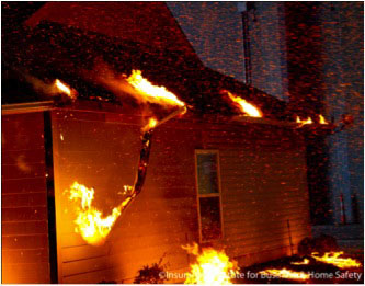
The direct flame contact from the burning mulch and gutter debris that fell to the ground caused the vinyl siding to deform and fall away from the wall, exposing the underlying sheathing. Flames from the ignited debris and near-building vegetation also resulted in a direct flame contact exposure to the fiberglass window screen covering the open window (Figure 10), allowing both flames and embers to enter the building. The entering flames and embers can easily ignite curtains and other interior furnishings. Ignition of the near-building mulch, and the damage from the resulting flame contact exposure to the side of the building, reinforces the importance of maintaining at a minimum a 0–5 ft low-or noncombustible zone near the home or building when vinyl and other combustible siding materials are used.

| Figure 10. The window screen failed as a result of the flame contact exposure from ignited mulch and vegetation. |
Re-entrant (Interior) Corners
Embers ignited the combustible mulch and vegetation located in the re-entrant corner shown in Figure 3. The wind flow in this corner resulted in rapid vertical flame spread upward to the soffited eave, impinging on the soffit material and strip vent (Figure 11). The aluminum soffit vent melted and flames entered the enclosed eave above the soffit. The fire was suppressed before any interior damage was sustained. The rapid upward spread of flames was likely exacerbated by the vortex (spiral motion) flow that was created in the corner. Creating a non- or low-combustible zone (e.g., irrigated lawn, use of non-woody (herbaceous) plants) in this area is critical. Use of noncombustible siding, trim and soffit / eave materials in this area would also be prudent.

| Figure 11. The mulch and vegetation in the re-entrant (interior) corner was ignited by embers, and subsequently ignited the combustible siding, resulting in rapid vertical flame spread to the soffited eave. |
Implications for Ember Exposures
This series of ember experiments clearly showed the potential for wind-blown embers to ignite vegetative debris that accumulates on a roof, in a gutter, or at the base of a wall, and combustible mulch products placed adjacent to the home. Ignition of these combustible materials will result in a flame contact exposure to adjacent materials, including siding, windows, materials at the edge of the roof, and even near-by vegetation.
Although additional experiments are needed, results to date have shown that gable end vents and eave vents in open eave construction are more vulnerable to the entry of embers than eave vents in soffited eave construction. The vulnerability of gable end vents suggests that foundation (crawl space) vents would also be vulnerable to ember entry. Although through-roof attic vents were not evaluated in this series of experiments, these results suggest that dormer-type through-roof vents would also be vulnerable to the entry of wind-blown embers.
Exposure to Radiant Heat
Human skin is much more sensitive to radiant heat than most building products. Whereas skin can develop severe burns in a matter of seconds when exposed to radiant heat of 15 kW/m2, wood can withstand 20 minutes or longer to this exposure before igniting. Therefore, the radiant heat level has to be high enough, and the exposure period long enough, for combustible building products to ignite or suffer other forms of degradation, such as glass breakage in a window. Exposure to lower levels of radiant heat can pre-heat a material, making it easier to ignite from a direct flame contact exposure. The objective of this series of tests was to improve our understanding of the sensitivity of exterior-use construction products to radiant heat. Once siding ignites, for example, the flames can either enter the building by first burning through a lap joint into the stud cavity, or by spreading laterally and vertically on the wall surface, impinging on windows and the eave area. The window glass any combustible eave material would be vulnerable to any flame contact exposure. Once the glass in a window breaks, embers can readily enter the occupied space of the building and ignite interior furnishings. Fire burning into the attic at the eave could also result in the loss of the home.
Radiant Panel Capabilities
The radiant panel was 50 inches wide and 63 inches tall (Figure 12) and consists of 50 infrared natural gas burner heads arranged in five rows of ten burners each. A 15 kilowatt per square meter (kW/m2) and 35 kw/m2 exposure was obtained at separation distances between the panel and the test assembly of 40 inches and 20 inches respectively. The tests reviewed here were conducted at the 35 kW/m2 level.

| Figure 12. The IBHS Research Center radiant panel consists of 50 infrared natural gas burners. The panel in this photograph is “on”. |
Window Tests
Tests were conducted on windows that used different framing materials, including wood, vinyl and aluminum, and different kinds of glass, including annealed (single and dual-pane units) and tempered (dual pane). Window “failure” can occur if the glass breaks or falls out or if the framing material ignites and the fire burns through the material into occupied space of the home. Testing at other research labs has indicated that the glass is the most vulnerable part of a window. IBHS tests supported that finding. These findings support the use of dual-pane windows – the failure mechanism included failure of the outer pane failed first with subsequent failure of the inner pane at later time. At the 35 kW/m2 exposure, neither of the panes in dual-pane tempered glass windows broke during the 25 minute exposure.
Curtains
Although other testing conducted separately on glass and curtain materials indicated that curtains located behind annealed glass and tempered glass commonly used today will not ignite before the window breaks (Babrauskas 2003), one objective of these tests was to demonstrate this in a laboratory. A vinyl frame, dual pane annealed glass window was exposed to a heat flux of 35 kW/m2 was used for this demonstration. A 100% cotton curtain was hung on the non-radiant heat side of the window. As shown in Figure 13, the curtain will ignite, but ignition occurred more than a minute after the upper section of the window fell out. The lower section stayed in tack during the test. This result supports the previous testing conducted separately on individual components – the glass breaks first, and then the curtain ignites.

| Figure 13. The 100% cotton curtain shown in this photograph ignited more than a minute after the upper section of the window fell out. The stand behind the burning curtain held the heat flux sensors. During the test, these sensors were positioned directly behind the upper and lower glass sections. |
Window Screens
Another goal of the window tests was to evaluate the contribution of screens in reducing the amount of radiant heat transmitted into the building. Both plastic-clad fiberglass and metal screens were evaluated on vinyl-frame, single-hung, dual-pane annealed glass windows. The screens were only positioned in front of the lower section since it was the only section that could open. The heat flux sensors were positioned behind the upper and lower sections of the windows. Results of these tests are shown in Figure 14.
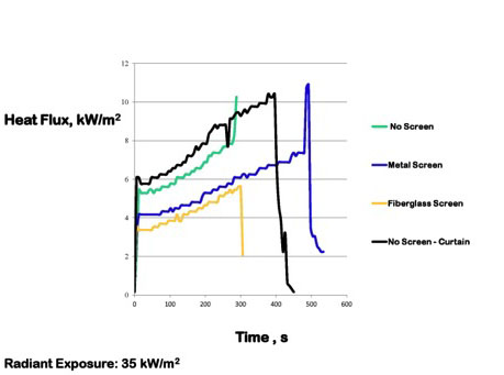
| Figure 14. A graphical presentation of the effect of window screens on the transmission of radiant heat through dual-pane windows. The upper most (black) line is from the window that was used in the curtain ignition test. |
The heat flux data from the screened windows are the lower two lines in Figure 14. These results indicated that window screens absorb radiant heat and thereby reduce the amount transmitted through the glass and into the occupied (living) space. In this case, the screens reduced the amount of transmitted heat by about one-third. Two other interesting observations can be observed. First, note that the measured heat flux behind the unscreened windows was less than 12 kW/m2, indicating that glass without screening was effective in reflecting or absorbing radiant heat. Second, the plastic clad fiberglass screen seemed to do a slightly better job than the metal screen, indicating that the metal screen may re-radiate heat back towards the window.
Siding
The wood siding products subjected to the 35 kW/m2 radiant heat exposure all ignited in times ranging from about 4.5 minutes to 16 minutes. Such a range in ignition times is not uncommon, particularly since the updraft created by the volatiles released by the wood and wood-based siding products extinguished the pilot flame located at the top of the 8 ft by 8 ft test wall sections. The time to ignition for the painted products was faster than that for the unpainted products. The time to ignition for the flat profile products (in this case a plywood T1-11 panelized siding product) was faster than that for the profiled siding product (in this case a solid wood horizontal lap siding product with a bevel profile).
Two different vinyl siding products were tested, including a standard product and a “heavy” product. These two products differed in their thickness, with the “heavy” product being about 0.01 in. thicker than the standard product. The response of both of the vinyl siding products to the imposed radiant heat exposure was similar. Neither ignited in flaming combustion but both started deforming immediately, exposing the underlying sheathing material about a minute into the test (Figure 15).

| Figure 15. As shown here, the vinyl siding deformed and fell away when exposed to the heat from the radiant panel, exposing the underlying wall (oriented strand board) sheathing. |
Implications for Radiant Heat Exposures
The 35 kW/m2 exposure level used in this series of experiments is relatively high. Cohen (2004) reported on a component of the large international crown fire modeling experiments that took place in the Northwest Territories, Canada between 1997 and 2000. As part of that larger study, Cohen set up wall assemblies at fixed distances from the edge of the burn plots. These assemblies were instrumented with heat flux sensors that measured the radiant heat from the fires. The resulting crown fires moved toward the wall assemblies and the heat flux was measured and recorded as a function of time. These results clearly showed that the measured heat flux at wall assemblies within 30 ft of a crown fire reached and exceed 35 kW/m2, however this level was maintained for at most one minute since the fire was moving so rapidly.
Since these results, and others (Babrauskas 2003), show that it takes minutes for most combustible products to ignite and for glass in windows to break at this exposure level, is building exposure to radiant heat really a problem? If you follow recommended vegetation management practices and are able to develop and maintain adequate defensible space zones, this level of radiant exposure is not likely to occur. When vegetation burns, it is typically a quick process, so whereas it may burn intensely, it will be for a relatively short time. Burning vegetation presents much more of a problem when it is close enough for the flames to actually touch the building (a flame contact exposure) or an attachment to the building, such as a deck. The intent of the defensible space is to significantly reduce the opportunity for the flames from a wildfire to reach your home and to reduce the opportunity for ember-ignited combustible vegetation and other combustible materials in the 5-30 ft zone from being able to threaten your home .
A scenario that can result in an elevated radiant exposure to your home for an extended period would be from the ignition of a nearby building. This could be a detached garage or outbuilding, or a neighbor’s house. Buildings are stationary – if they ignite, they burn in place (Figure 16). Figure 17 shows the side of a home located about 40 ft from another home that ignited and burned to the ground during a southern California wildfire. The “wildfire” exposure to this house was largely radiant heat from the neighboring home. Vegetation between the two homes was larger, well pruned pine trees which survived, and Manzanita that was located about 20 ft from the damaged home. The surviving home suffered considerable damage, but it wasn’t destroyed. This home was clad with vinyl siding that had been installed over an existing solid wood siding product. After vinyl siding drops off, the home must rely on underlying sheathing materials for protection from radiant heat, direct flame contact and ember exposures. The remnants of the remaining vinyl siding can be seen in Figure 17 at the upper left corner of the window. The window glass was dual pane, annealed. The outer pane of the dual pane window broke and fell out but the inner pane remained in place.

| Figure 16. This building was ignited and allowed to burn to the ground during a volunteer fire department training activity. Although the fire took hours to completely burn, the highest radiant heat exposures occurred during a 45 to 60 minute period. |

| Figure 17. The side of this home was damaged as a result of a radiant exposure when a neighboring home burned to the ground. Note the remnants of the vinyl siding (circled) and the broken outer pane of a dual pane window. |
References
Babrauskas, Vytenis. 2003. Ignition Handbook. Fire Science Publishers, Issaquah, WA. 111g pp.
Cohen, Jack D. 2004. Relating Flame Radiation to Home Ignition Using Modeling and Experimental Crown Fires. Canadian Journal of Forest Resources 34:1616-1626.
Manzello, Samuel L., John R. Shields, Thomas G. Cleary, Alexander Maranghides,
William E. Mell, Jiann C. Yang, Yoshihiko Hayashi, Daisaku Nii, and Tsuyoshi Kurita.2008.
On the development and characterization of a firebrand generator. Fire Safety Journal 43: 258–268
Manzello, Samuel L., Seul-HyunPark, SayakaSuzuki, JohnR.Shields, YoshihikoHayashi. 2011.
Experimental investigation of structure vulnerabilities to firebrand showers. Fire Safety Journal 46: 568–578.